Saw Blade Wear Cutting Gypsum Board
Saw Blade Wear Cutting Gypsum

End of gypsum board – notice saw marks

Two saw blades – top one is as removed. Bottom one has been cleaned for inspection
Theoretically these blades have been sawing gypsum however an analysis reveals a large amount of other minerals.
|
X-ray Diffraction Data |
|
|
|
|
Rough |
|
|
|
XRD# |
101 |
102 |
103 |
104 |
Mohs |
Hardness |
|
|
Sample # |
1 |
2 |
3 |
4 |
Hardness |
Comparison |
|
|
Gypsum |
86.70% |
91.40% |
93.80% |
93.40% |
2 |
Cadmium, Bismuth |
|
|
Anhydrite |
9.80% |
2.90% |
2.10% |
1.20% |
4 |
Iron, Nickel, Platinum, Steel |
|
|
Quartz |
0.80% |
1.70% |
0.50% |
0.70% |
7 |
Quartz, Vanadium |
|
|
Illite&Mica |
1.40% |
0.90% |
0.50% |
0.80% |
1 - 2 |
lead soft |
|
|
Kaolinite |
0.50% |
0.40% |
0.00% |
0.40% |
2 - 2.5 |
gold, silver |
|
|
RO M-L I/S 60S* |
0.80% |
2.70% |
3.10% |
3.50% |
|
|
|
|
TOTAL |
100.00% |
100.00% |
100.00% |
100.00% |
|
|
|
Gypsum has a Mohs hardness of 2. Some of the other minerals are in the same range. There are two minerals that are much harder than Gypsum and this is a big part of the wear issue.
|
Anhydrite |
9.80% |
2.90% |
2.10% |
1.20% |
4 |
|
Quartz |
0.80% |
1.70% |
0.50% |
0.70% |
7 |
|
Hard bits anhydrite and quartz |
10.60% |
4.60% |
2.60% |
1.90% |
|
I photographed the first ten tips at 50x and 200x.
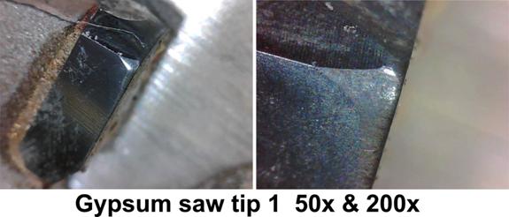

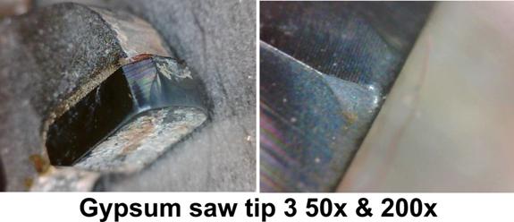
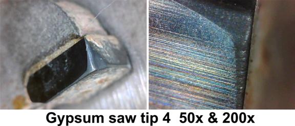
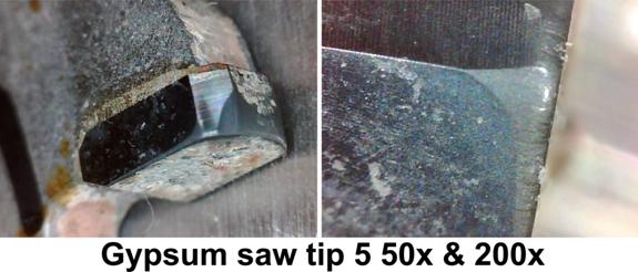
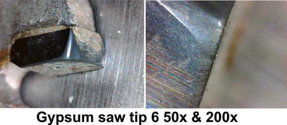
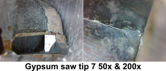
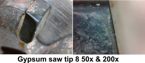
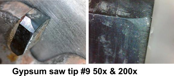
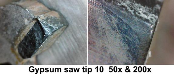
The 50x photographs show the kind of wear you would expect from cutting a highly abrasive material. It is a smooth, shiny, polished surface.
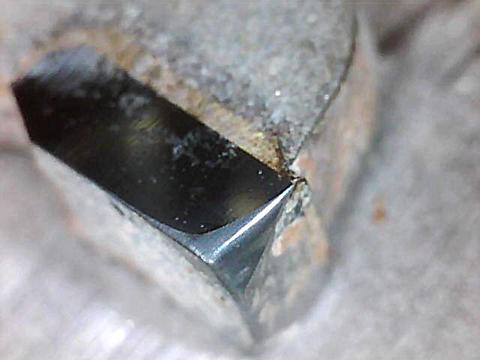
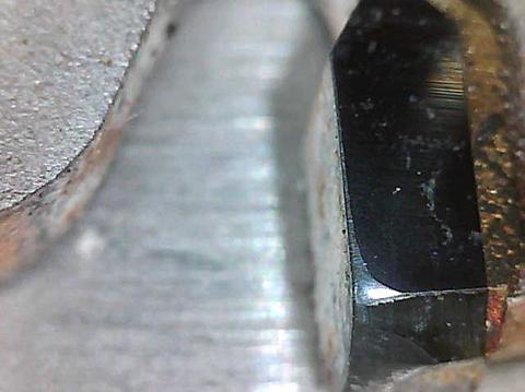
At 200x you still see the smooth, polished surface but you also see some very significant gouges in the edges of the tips. Plus you can see a general roughness to the cutting edge.
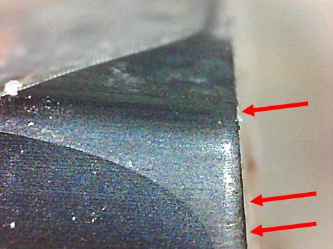
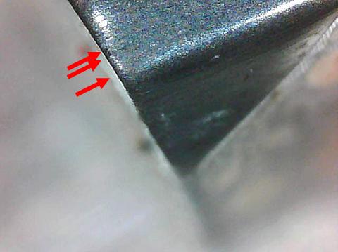
For comparison, following is a picture of the jaws of a dial caliper at 0.001”
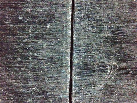
The fine, abrasive material is wearing the carbide greatly. However the wear from the fine, abrasive gypsum is greatly aided by damage from the hard particles such as anhydrite and Quartz.
It appears that the hard minerals are actually gouging out some of the carbide in some cases. They are also causing nicks in the edge. There does not appear to be any spalling or chipping, at least at 200x.
Each gouge or edge nick does at least tow things to exacerbate the wear. First it increases the wear surface. Wear is a square / cube relationship. Wear occurs along a surface area (square) of a mass (cube). One of the limiting factors in wear rate is the available surface area. If you have a surface area of 4 and a mass of 8 then the part will be worn down at a certain rate. If you increase that surface through chips, gouges, etc. then it wears faster. You might have a ratio 5 (square or surface) to 8 (mass or cube).
How Carbide Wears
Tungsten carbide is actually tungsten carbide grains cemented with a metal, usually cobalt. What follows are failure mechanisms we have seen in industry.
1. Wear – the grains and the binder just plain wear down
2. Macrofracture – big chunks break off or the whole part breaks
3. Microfracture – edge chipping
4. Crack Initiation – How hard it is to start a crack
5. Crack propagation - how fast and how far the crack runs once started
6. Individual grains breaking
7. Individual grains pulling out by mechanical means
8. Chemical leaching that will dissolve the binder and let the grains fall out
9. Rubbing can also generate an electrical potential that will accelerate grain loss
10. Part deformation - If there is too much binder the part can deform
11. Friction Welding between the carbide and the material being cut
12. Physical Adhesion – the grains get physically pulled out. Think of sharp edges of the grains getting pulled by wood fibers.
13. Chemical adhesion – think of the grains as getting glued to the material being cut such as MDF, fibreboard, etc
14. Metal fatigue – The metal binder gets bent and fatigues like bending a piece of steel or other metal
15. Heat – adds to the whole thing especially as a saw goes in and out of a cut. The outside gets hotter faster than the inside. As the outside grows rapidly with the heat the inside doesn’t grow as fast and this creates stress that tends to cause flaking (spalling) on the outside.
16. Compression / Tension Cycling - in interrupted cuts the carbide rapidly goes though this cycle. There is good evidence that most damage is done as the carbide tip leaves the cut and pressure is released.
17. Tribology – as the tip moves though the material it is an acid environment and the heat and friction of the cutting create a combination of forces.
Notes:
1. As with any chemical reaction of this sort the acids create a salt that protects underlying binder until the salt is abraded away so grain size and binder chemistry are also important.
2. Electrochemical effect – erosion compounded by the differences in electrical resistivity between carbide and cobalt
3. Heat from rubbing can affect carbide so a slicker grade can increase life.
Recommendation:
The carbide needs to be much tougher so that it doesn’t gouge and chip as readily. Plus it needs hardness for survivability from abrasive wear.
|
|
|
| Standard Carbide |
Cermet II monolithic binder |
Our Cermet 2 grade starts out as a hard carbide and then goes through a post sintering process by which the parts are infused with a Boron metalloid. This makes the parts behave much more like a monolithic part than a cemented part. It is sort of like adding rebar to concrete but on a molecular level.
It changes the chemistry which greatly increases its resistance to chemical attack and helps it resist electrochemical effects caused by the extreme rubbing in this application.
This material brazes and grinds like ordinary C-4 carbide. It is well proven and provides between 2 and 10 times the life of ordinary carbide depending on the application. This is an extreme application and performance towards the lower end should be expected.


